Initial regulator tests looking good!
Our initial rev1 PCB design of the Helicopter Brain Prototype (HBP) had some issues with the regulator circuit. Once we got the boards back from the assembler, we quickly found out that you can connect all the right pins and still have a non-functional regulator. Apparently, thick traces and minimal vias are very important. Without a working regulator, you can’t power the other components on the PCB, so the HBPv1 boards could fly =(.
Therefore, the major improvement for the HBPv2 boards is to have a working regulator. Unfortunately, there’s no way to know your circuit will work until you fabricate the PCB and solder all the components to it. We have very strict weight limits since the HBP is attached to a flying toy helicopter, and this makes our boards expensive to fabricate. We use tiny parts, both because they are lighter and because they take up less room on the PCB, making the PCB lighter. But, PCBs for small components cost more, and any issues with the PCB design get expensive.
The HBPv2 PCBs came in, as well as the components to solder to the PCB. The regulator is a small, square package, and all the pins are on the bottom, not on the side. This makes using a soldering iron impossible. Instead, I painted each pad on the PCB with solder paste (microscopic spheres of solder suspended in liquid). My brush was literally a sewing pin, and used under a high powered microscope. That one chip had 21 pads (5 on a side and large pad in the center), and took over an hour to paint. When I finished painting, I delicately dropped the regulator chip on top using tweezers.
There were also a number of tiny passives (capacitors, resistors). Some very precise people can solder these “0402” parts, but I’m not one of them. I instead painted solder on their pads and dropped them down like the regulator chip. A few hours later, that was done.
The next step was to put it in a “toaster.” This is a fancy small over that heats up the PCB and causes the solder to melt and attach to the components dropped on top. The toaster has a “heat profile” programmed in, meaning that it controls the temperature, such that the PCB is heated at certain temperatures for specific amounts of time. Our toaster is rather strange in that the menu system is in Chinese, and some other people have figured out the correct sequence of buttons to press. But it seems to work reliably, so it’s a small price to pay.
Eight minutes later, the components appeared to be soldered nicely to the board. All of the regulator components are on the left side of the board, as shown here:
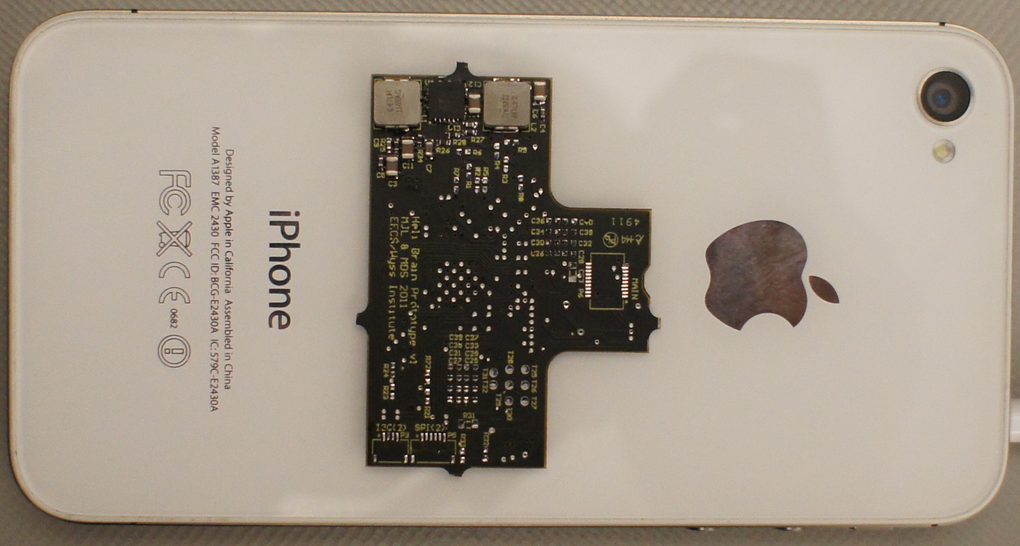
HBPv2 assembled regulator
I then hooked the regulator up to the battery voltage and verified it correctly regulated 1.0V and 3.3V, necessary to power the other components on the HBP. I’m happy to say that it worked. Here’s video proof:
We have yet to try regulating under a load, so it’s totally possible that the regulator will collapse as soon as we try to power anything. Hopefully that will not be the case, and we should be able to test this tomorrow. On most of the HBPv1 boards, the regulator couldn’t even generate either voltage without a load, so we’ve improved at least. I’ll also be verifying all of the remaining pins on the board are properly routed using a multimeter tomorrow. Hopefully everything else works too =).